| Heater Installation |
.jpg) |
SAFETY PRECAUTION This sign warns of serious injury, damage to property and potential death. Before operating, please read the following “Safety Precautions” carefully. |
||||||||||||
|
|
IMPORTANT
|
||||||||||||
| CAUTION |
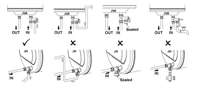
Ensure the inlet pipe is at the lower position (Refer figure A). |
| CAUTION |
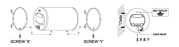
This appliance is designed for vertical mounting to the wall only. |


.jpg)
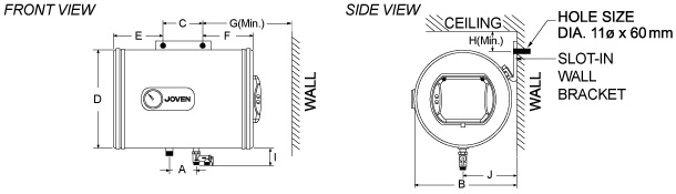
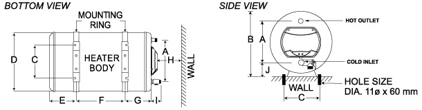
| SPECIFICATIONS | |||||||||||||
| Model | Tank Capacity Litres (Imp. Gals) | Dimensions (mm) |
Approx. Wt. Kgs (Empty / Full) |
||||||||||
| A | B | C | D | E | F | G | H | I | J | ||||
| JH 15 | 15 (3.3) | 260 | 405 | 265 | 381 | 96 | 70 | 96 | 350 | 65 | 92 | 10 / 25 | |
| JH 25 | 25 (5.5) | 260 | 405 | 265 | 381 | 121 | 150 | 121 | 350 | 65 | 92 | 12 / 37 | |
| JH 35 | 35 (7.7) | 260 | 405 | 265 | 381 | 121 | 269 | 121 | 350 | 65 | 92 | 14 / 49 | |
| JH 38 | 38 (8.4) | 260 | 405 | 265 | 381 | 121 | 304 | 121 | 350 | 65 | 92 | 15 / 53 | |
| JH 50 | 50 (11.0) | 260 | 405 | 265 | 381 | 121 | 438 | 121 | 350 | 65 | 92 | 17 / 67 | |
| JH 56 | 56 (12.3) | 260 | 405 | 265 | 381 | 121 | 508 | 121 | 350 | 65 | 92 | 18 / 74 | |
| JH 68 | 68 (15.0) | 260 | 405 | 265 | 381 | 121 | 648 | 121 | 350 | 65 | 92 | 20 / 88 | |
| JH 91 | 91 (20.0) | 260 | 405 | 265 | 381 | 121 | 914 | 121 | 350 | 65 | 92 | 25 / 116 | |
| JVA 25 | 25 (5.5) | 100 | 393 | 217 | 372 | 121 | 271 | - | 316 | 65 | 77 | 12 / 37 | |
| JVA 35 | 35 (7.7) | 100 | 393 | 217 | 372 | 121 | 390 | - | 316 | 65 | 77 | 14 / 49 | |
| JVA 50 | 50 (11.0) | 100 | 393 | 217 | 372 | 121 | 559 | - | 316 | 65 | 77 | 17 / 67 | |
| JHT 35 | 35 (7.7) | 100 | 385 | 100 | 381 | 206 | 206 | 450 | 120 | 58 | 170 | 14 / 49 | |
| Plumbing Connection |
|
|||||||
.jpg)
|
A. Cold Water Inlet from Main Supply / Water Tank B. Control Valve (Not Included) C. Single or Double Check Valve (Not Included) D. Pressure Relief Valve |
E. Drain Valve (Must Not Be Closed / Blocked) F. Overflow Pipe to Drain or Floor Trap G. Hot Water Outlet to Mixer Tap |
|
|||||||
|
|
|||||||
|
A. Cold Water Inlet from Main Supply / Water Tank B. Control Valve (Not Included) C. Single or Double Check Valve (Not Included) D. Pressure Relief Valve |
|||||||
|
TO FILL HEATER TANK
|
|||||||
| Electrical Connection |
|
|
IMPORTANT
|
|||||
| HEATER ELECTRICAL LOADING | MINIMUM CONDUCTOR SIZE | ||||
|
Voltage (Va.c.) |
Power (kW) |
Conductor Size (mm2) | |||
| 220 to 240 | 1.37 to 1.63 | 2.0 | |||
| 2.50 to 3.00 | 2.5 | ||||
 |
|
|||||
| Operating Procedure |
|
|
|
|
The first operation and heating of the appliance must be observed by the installing technician after water and electrical connection have been made and heater tank filled with water, before switching on the electrical supply. Installation of storage water heater - Isolation barrier - ultimate safety for storage water heater - hot water piping installation - Stainless steel stopcock - Safety valve - Drain Pipes - Check Valve - Not Included Wiring Point - 1 year installation warranty |
|


BWS Sales & Services Sdn Bhd is specialized in Solar Water Heater, Water Pressure Pump, Water Filtration System and Swimming Pool for both residential and commercial market in single unit or bulk order. Our main office is located in Seri Kembangan, Selangor, Malaysia.